
ABOUT THIS PROJECT
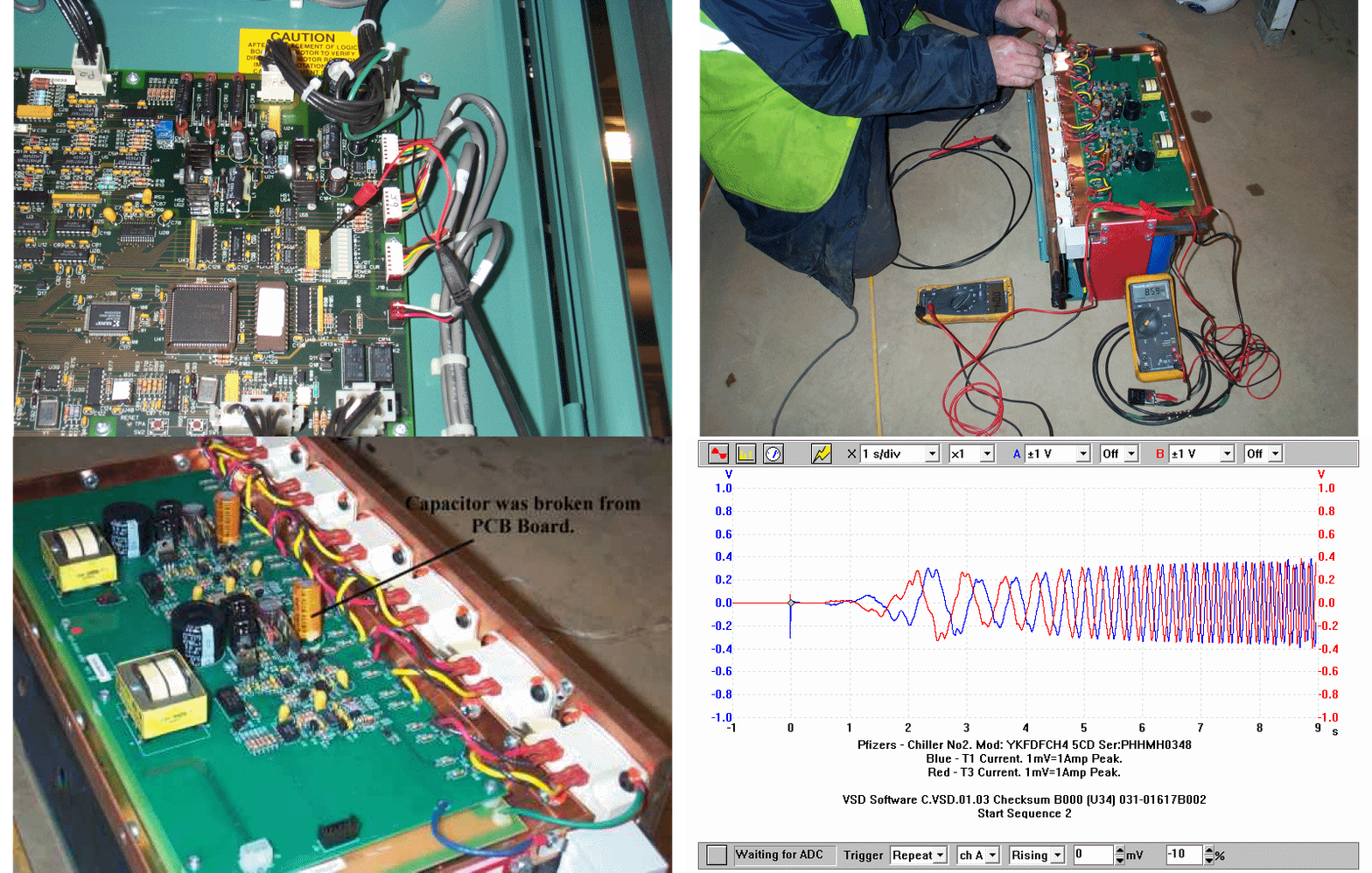
We attended site with multiple multi meters and 9 VDC Batteries for testing the SCR’s and IGBT assemblies, a gate switching fault soon became apparent. On carrying out the IGBT Gate Test Procedure developed by us in-house, it was found that the Pole Assembly Phase C Positive (+) Gate LED was not operating correctly. It would start High then switch Low and stay Low. The Minus (-) Gate LED would gate correctly. This would make a short circuit on the DC Link via the IGBT’s bridge; if the DC Link were charged, this would instigate the ‘SCR Rectifier Failure Alarm’ as seen on site.
We removed Phase C Pole Assembly and inspected the IGBT Gate Trigger Board where we found the (+) Gate 15 VDC Gold Capacitor with heavy mechanical damage. It looked like the capacitor was damaged on the PCB Card during insertion of the Pole Assembly into the cabinet; where with running vibration subsequently failed the component.
We sourced a replacement IGBT Gate Trigger Board and reassembled the Pole Assembly. A final component and wiring check was completed, which found no other problems.

